
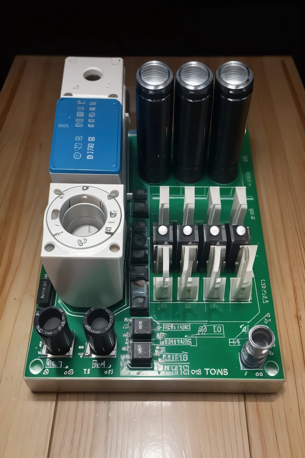
A close up of a circuit board with a few electronic components


Prompts
Copy
Mesh Circuit Diagram on Breadboard Description:
Please
,
creates an image of a circuit on a breadboard with the following characteristics:
1
.
Components:
• 4 resistors of 330 ohms (R1
,
R2
,
R3
,
R4)
• 3 voltage sources (12V
,
9V
,
y 12V)
• Breadboard with top feed rows (+) and lower land (-)
• Connection cables 2
.
Circuit Diagram:
Top Row (+) GND (-)
---------------------------------------------------------
| 12V (E1) | | 9V (E2) | | 12V (E3) | GND |
| | | | | | | | | |
| R1 |----> | R2 |----> | R3 |----> | R4
| | | | | | | | | |
| | | | | | | | | |
---------------------------------------------------------
Bottom Row (-) GND (-)
3
.
Connection Steps:
• Connect one end of R1 to the top 12V row (E1) and the other end to a node in column 5
.
• Connect one end of R2 to the same column 5 where R1 ends
,
and the other end to a column 10
.
• Connect one end of R3 to the same column 10 where R2 ends
,
and the other end to a column 15
.
• Connect one end of R4 to the same column 15 where R3 ends
,
and the other end to the bottom row (GND)
.
• Connect the positive terminal of E1 to the top 12V row and the negative terminal to column 5
.
• Connect the positive terminal of E2 to column 10 and the negative terminal to column 15
.
• Connect the positive terminal of E3 to column 15 and the negative terminal to the bottom row
INFO
Checkpoint & LoRA

Checkpoint
Realisian
0 comment
0
0
0
SeaArt Swift AI Apps
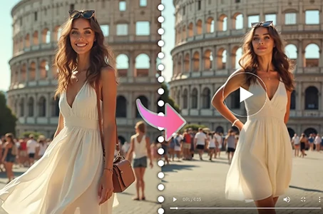
AI Video Generation
Unleash your imagination and let AI create visual wonders for you
Face Swap Online Free
Create funny or realistic face swap videos & photos in a snap
Disney Filter
Instantly transform your photos into Disney characters.
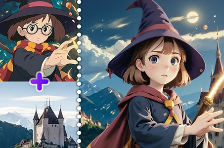
AI Image Fusion
Combine two images into new one stunning visual with AI Image Fusion.
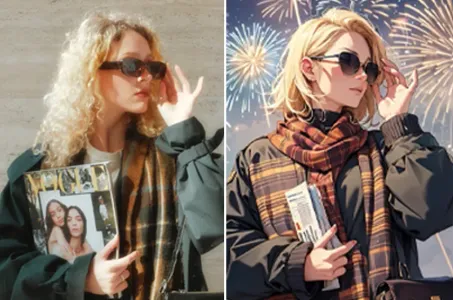
AI Filters
Turns every photo into a work of art
AI Dance Video Generator
Play with this AI dance video generator, unleash your inner dancer instantly!
Explore More AI Apps